Senior Capstone Project (July - December 2017)
|
My responsibilities and skills demonstrated
Quick Attach and Release Mechanism Interfacing with Vehicle Console

Project Management Gantt Chart
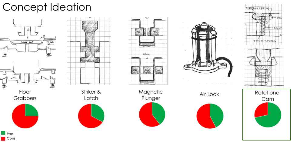
Top Five Designs
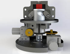
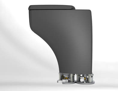
Final 'Rotational Cam' Design
The team
|
Purpose
Our team of five senior mechanical engineers was asked by a sponsor to create a quick attach and release mechanism to interface with a vehicle's floor and various components in a vehicle. The idea behind our mechanism was to demonstrate opportunities for modular interior systems in future autonomous vehicles. Design To start, the team first outlined the design criteria upon which they wanted to create their mechanism. We designed for the following: Safety
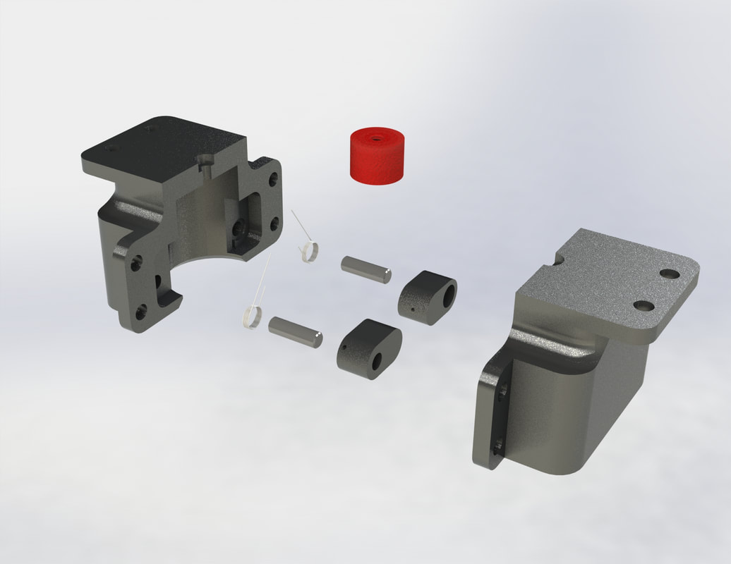
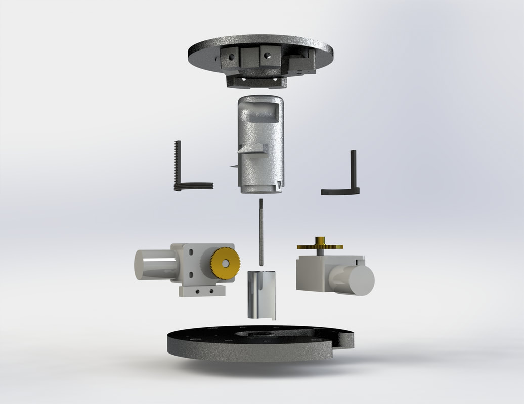
The team brainstormed over 15 ideas and narrowed them down to their top five using a weighted design matrix. The team further chose their final design after discussing in detail each of the five design and the challenges that would come with each design. After selecting the 'rotational cam' design we performed initial hand calculations for shear stress using a factor of safety of 10 to determine the necessary size of our mechanism in order to sustain various crash scenarios. These calculations drove initial designs created using SolidWorks. After multiple iterations and design reviews, the team created a final prototype of the 'rotational cam,' powered by two motors. 'Rotational Cam' Design The 'Rotational Cam' Design consisted of two subsystems, a component assembly (which would attach to the modular component) and a floor assembly (which would attach to the vehicle's floor). The component assembly consists of two housings which are bolted together, creating a cavity for the plunger in the floor assembly to be inserted into. Additionally, there is a rubber bumper, and torsioned pawls which lock the plunger in place once it is inserted. The floor assembly consists of a plunger which comes out of the floor for engagement of the modular component, an alignment key which allows for precise rotation, a top plate, and a base plate. The plunger is powered by two motors, one for up-down motion and the other for left-right motion. When a user wants to install a modular component, the plunger will come out of the floor and rotate 90 degrees clockwise. The component may be engaged with the plunger by simply pushing down on the component, locking the pawls in place. The component is removed by rotation the plunger in the counter-clockwise direction 120 degrees, forcing the pawls out of the sweep feature. At that point, the pawls will be completely vertical and the component can easily be removed. The plunger will then rotate 30 degrees in the clockwise direction and the up-down motor will pull the plunger back into the floor. Analysis of the system was done using SolidWorks FEA to apply different loading scenarios to the floor assembly. A conservative approach was taken, assuming one plunger per component would be used. FEA drove a material change from Al 6061 to Al 7075 for the plunger. FEA also showed stress concentrations, driving design change recommendations. Conclusions and Recommendations We believe that our design fulfills our problem statement and has the potential to be implemented into future vehicles. Our prototype adheres to safety regulations, integrates seamlessly with the interior floor a vehicle, and is innovative and intuitive to use. Moving forward, we believe that the design can be improved by integrating a single motor for both left-right movement in addition to up-down motion. This would save cost and added weight to the vehicle. Additionally, reducing to one motor would reduce the footprint of the design. Further, we would have loved to have had the opportunity to work with and test machined parts. Due to time constraints on the project we were not able to test or simulate an actual user experience. |